The ends justify the tests in failure analysis
Why we need to ask the right questions in failure analysis.
Failure analysis is crucial to maintaining and improving the integrity, reliability and safety of products and materials. It not only uncovers the underlying reasons for failure but also provides insights to optimise designs and manufacturing processes. This avoids costly recurrences.
Failure analysis demands that the right questions are asked to determine the root cause. The answers to these questions will prompt the use of suitable inspection and testing techniques in future developments – both as stand-alone assessments and sometimes in novel combinations.
To select these inspection and testing techniques, we need to understand what information we might obtain from each of them and whether or not this is relevant to the issue at hand.
Unlike most industrial requirements, failure analysis often requires a combination of inspection and testing categories in unexpected, interesting and/or innovative ways to determine causation.
In terms of broad categories, testing might be undertaken to:
- Identify and analyse flaws and imperfections.
- Measure precise dimensions of items, products and components.
- Determine the elemental and chemical composition of materials.
- Examine the internal structure of materials (e.g. for metals to identify grain size, phases and orientation).
- Assess the mechanical properties of materials.
- Measure the functional performance of a product or system.
- Assess the manufacturing method/route for a component or system.
It is important that the process follows specific steps. This ensures that evidence is captured, recorded and evaluated in a controlled manner and, when required, the inspection and testing are performed in accordance with applicable standards. This is required to justify conclusions reached and is demonstrated by the following case studies.
The problem of the seized valve
What appeared at first to be an open-and-shut case of simple tests and measurements, eventually included compositional analysis and even incubation of a bacterial culture of unlikely deposits.
A pressure independent control valve was operating incorrectly. These are used in closed-loop water systems in buildings for accurate control of water flow rate and water pressure.
An affected valve was disassembled and sectioned in half to inspect and measure the internal components. This revealed the seizure of some moving nylon components, as their surfaces were covered in a film of white deposits. Other components made from steel and brass were not affected in the same way.
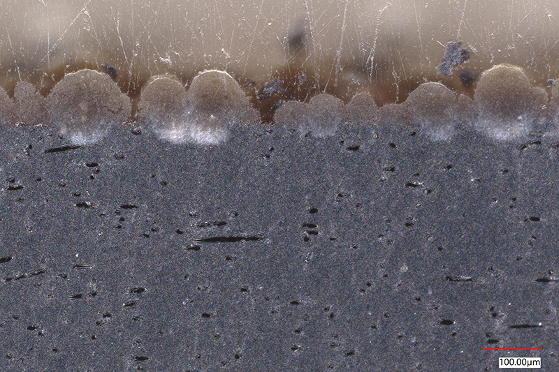
These deposits consisted of small spheres, with diameters of approximately 20-200µm. They had agglomerated to form a film and the build-up was found to exceed the required clearance tolerance. This appeared to be the root cause of the moving components getting stuck in service.
Mounted cross-sections of the nylon surface were prepared. This revealed that the spheres had slightly ‘penetrated’ into the surface. As shown in the image on p28, this is a feature that would probably have provided mechanical stability to the spheres, ‘binding’ them on the surface.
The question remained, where did the curious spherical deposits originate from? To answer this, compositional and microstructural testing methodologies that were not originally envisaged became essential.
Samples of the deposits were carefully scraped off from the valve components and analysed in a scanning electron microscope (SEM) coupled with an energy dispersive X-ray (EDX) spectrometer. The EDX results revealed that the deposits were predominantly calcium carbonate.
This led to suspicion that a biological material was present. By dissolving the calcium carbonate in hydrochloric acid and examining the remaining residues by microscopy, this was confirmed.
To investigate this biological presence further, samples were cultured from the deposits and the system water. This test confirmed that nitrite-reducing bacteria (NRB) and Pseudomona (a saprophytic bacterial genus commonly found in water and soils; several species are known to cause illness in humans) had been detected in the water samples. Research revealed that a nitrite-based corrosion inhibitor was used in the water system, which would have acted as a food source for the NRB.
As such, it appeared that bacteria in the system had established themselves on nylon surfaces, where it is easier for them to populate than bare metal. The bacteria would have been sustained by nitrites in the water and may also have gained sustenance from the underlying nylon. The bacteria then acted as nucleation sites for calcium carbonate, eventually leading to seizure of moving nylon components.
The root cause of the valve seizure was therefore determined to be the presence of microbes in the closed-loop water system due to poor water quality management – most probably inadequate dosing and/or inappropriate selection of water treatment chemicals.
A concrete case of contaminated water
Diligent inspection and testing can reveal far more than initially anticipated.
Benzyl alcohol contamination was detected in water transported by a newly installed pipeline. Its source was unknown. The pipeline consisted of a steel casing with internal spun cast mortar coated with an internal epoxy layer.
Three sectional samples cut from various parts of the pipeline were visually inspected and compared. Distinct differences in the internal coating layers were found between samples.
This was unexpected as the samples were allegedly from the same manufacturer and manufacturing route, so should have been similar in construction and appearance. The coatings were then evaluated using optical microscopy.
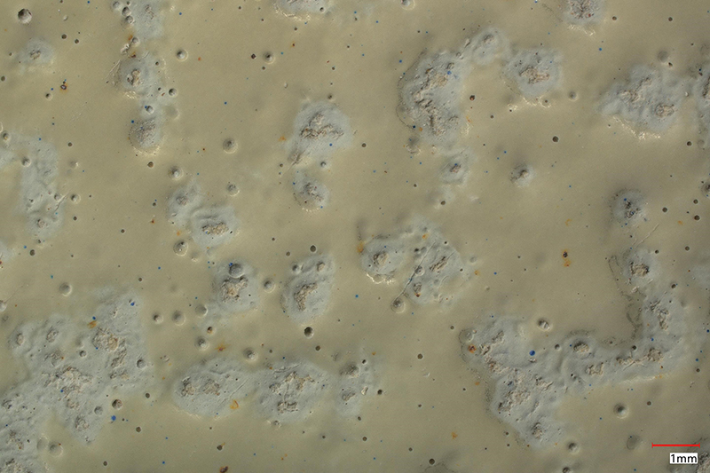
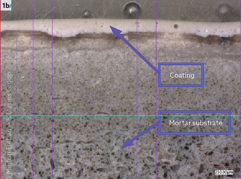
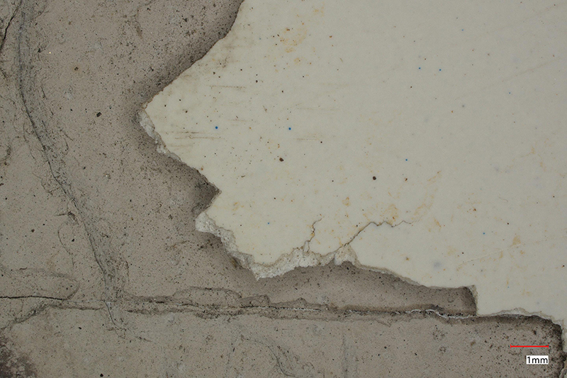
Sample 1, see below, showed a well-adhered, albeit discontinuous, coating on a solid mortar substrate.
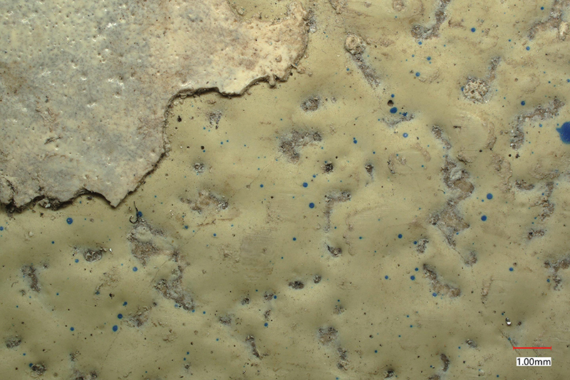
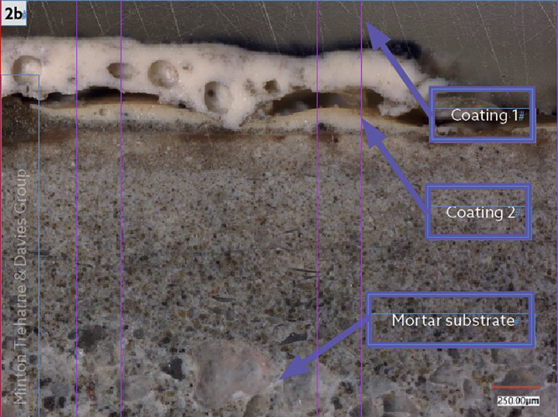
Sample 2, see below, showed a well-adhered, albeit porous and discontinuous, coating on a solid mortar substrate. Remnants of a second coating with poor adhesion was noticed over the first coating.
© Minton Treharne & Davies Group
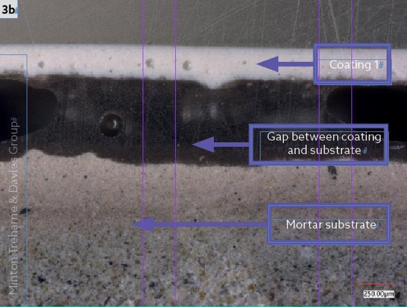
Sample 3, see images below, showed one coating with poor adhesion to a friable mortar substrate.
© Minton Treharne & Davies Group
The mortar layers of all samples were analysed by inductively coupled plasma optical emission spectroscopy (ICP-OES) – an analytical technique used to detect chemical elements. The results showed that the friable layer from the third sample had twice the calcium and half the silicon content of the mortar in the other samples. This indicated that the friable layer was almost pure cement, depleted of aggregate, resulting in poor mechanical properties.
All the coating layers were analysed by fourier transform infrared spectroscopy (FT-IR) to determine whether or not they were similar. The results showed that the coatings on samples one and two were the same while the second coating on sample two and the coating on sample three were different.
To determine the source of the benzyl alcohol, all the coatings were analysed by pyrolysis gas chromatography mass spectrometry (PyGC/MS).
PyGC/MS is an analytical technique used to study the composition of complex materials by thermally decomposing them into smaller, volatile fragments (pyrolysis), and then separating and analysing these fragments.
The PyGC/MS analysis showed that only the coating on sample three contained benzyl alcohol. This was then quantified and determined to be present at a level of 3%.
The primary puzzle was solved. However, the investigation had also uncovered other manufacturing issues – poor coating quality and weakened cement. This would have probably resulted in poor water quality and premature pipeline degradation during service.
The investigation ensured that the water contamination could be eliminated and that process control on the manufacturing of future pipelines could be improved.
A shot in the dark
Sometimes the issue at hand is not always visually apparent. An investigator must apply their expertise to reveal hidden issues and to eliminate unnecessary investigation and testing.
Non-destructive testing (NDT) can make a world of difference in revealing an underlying issue. However, the application of exploratory NDT is not always possible in accordance with standard techniques. To obtain clear and meaningful results, it is necessary to understand the fundamental principles.
During routine machining of standard bolt holes in a forged flange component, surface breaking discontinuities were visually observed. Exploratory inspection by ultrasonic testing (UT) and radiographic testing (RT) aimed to determine whether these discontinuities were indicative of a larger issue.
The UT indicated that subsurface indications were present but the extent of the indications could not be quantified reliably, and the inspection was therefore supplemented with RT. Radiographing components with complex internal geometries (in this case numerous bolt holes) leads to a phenomenon termed ‘radiation scatter’.
Radiation scatter occurs due to radiation being deflected around the internal surfaces of holes, and consequently results in a poor-quality blurred image. This is where out-of-the-box thinking can help solve a problem.
By filling the nearby bolt holes with lead shot, the unwanted radiation was eliminated, removing the scattered image and giving a sharper radiograph of the areas inspected.
The surface breaking discontinuities are associated with major sub-surface inclusions that compromised the integrity of the flanges.
What lies beneath
Radiography can also be used to evaluate large areas to determine the extent and severity of damage. Such large-scale work was conducted on a cast-iron pipe spool containing a full-length crack.
Exploratory radiography along the crack and 20cm either side revealed a large decrease in pipe density over a substantial area. Removal of coupons and their visual inspection confirmed that the reduction in density was a consequence of graphitic corrosion, shown in the image below.
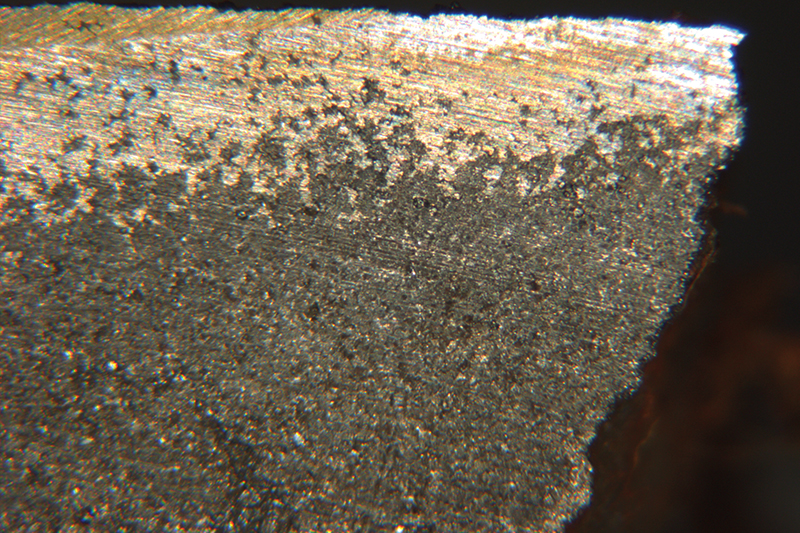
This is a form of corrosion in which the iron matrix is selectively corroded away, leaving behind a weakened structure composed primarily of graphite. The result is a material that retains its shape but loses its mechanical strength and becomes brittle, often leading to failure.
In this case, radiography and sectioning eliminated the need for further mechanical testing and was used to show that the problem was present throughout the pipe’s length, such that repair was not possible.
Failure analysis often involves a combination of inspection and testing techniques applied in innovative ways to identify the root causes.
The selection and application of the best methods, or combinations of methods, depend on asking the right questions. Critically, evaluating the answers will push us towards the ultimate prize. The truth.