Plasticity modelling testing
How can finite element modelling challenge the status quo of plasticity testing? Dr James Dean and Professor Bill Clyne FIMMM of Plastometrex give us the lowdown.
Mechanical testing constitutes a large industrial sector in its own right. Much of this activity is focused on the plasticity of metals, which largely determines their strength. Plasticity depends in a complex way on microstructure, which, in turn, is sensitive to composition, impurities and thermo-mechanical treatments.
This sensitivity means that experimental characterisation of plasticity has to be repeatedly carried out for quality control, performance monitoring and material development. Currently, the two main approaches for verifying plasticity are tensile testing and hardness measurement, which have remained essentially unchanged for a century. While mature, they suffer from serious drawbacks and it seems time for a new approach using the increasingly ubiquitous power of finite element modelling (FEM).
The impact of necking
The plastic response of a metal is fully captured by its true stress – the true strain relationship. The main outcome of a tensile test is the load-displacement data. This can readily be expressed as a nominal stress – nominal strain plot – which can in turn be converted to a true stress versus true strain relationship.
However, the conversion assumes the sample is deforming uniformly, within the gauge length, throughout the test. In practice, necking commonly occurs, perhaps from an early stage and quite possibly without it being apparent visually. Furthermore, while necking does not affect the yield stress, it determines the peak (nominal) stress, commonly termed the ultimate tensile strength (UTS) and the ductility (nominal strain at fracture). In fact, the latter is strongly influenced by the final stages of necking and is hence dependent on the sample dimensions.
Also, tensile testing is a cumbersome and destructive procedure, requiring extensive machining to produce the sample, and involves various practical difficulties. Although regarded as the gold standard of mechanical testing, it is far from ideal.
A hard nut to crack
Hardness testing is much easier than tensile testing. A hard indenter with a given shape is pushed into a sample with a known force. The size (commonly the lateral extent) of the resultant indent is measured, often using a low-power optical microscope. This refers only to the size of the indent. The force is known (predetermined), but just the size is measured as an outcome.
The equipment is relatively simple, the procedure is quick and easy and because it is a non-destructive test the sample can be small, needing little preparation, and local variations can be examined. These are all highly attractive features that are not exhibited by tensile testing. However, there is a major drawback in that there is no obvious relationship between the number obtained and the true stress-strain curve of the metal. The value varies for different types of hardness tests and for the same type with different loads. Despite the various correlations that relate hardness numbers to yield stress, UTS and even fracture toughness, it is only a semi-quantitative indication of the resistance that the metal offers to plastic deformation. It is a world away from tensile testing and rigorous characterisation of plasticity. Of course, the underlying problem is that stress and strain fields can evolve in a complex manner during an indentation.
Best of both worlds
The outcome of an indentation test – the size and shape of the residual indent – depends sensitively on the true stress-strain curve of the material, potentially over a large range of plastic strain. While extracting only a single measurement of the indent diameter is simple experimentally, it exploits only a minute proportion of the information incorporated into this residual profile.
Measurement of the full profile now forms the basis of a new methodology for obtaining complete (true) stress-strain curves from indentation experiments. This is termed ‘indentation plastometry’. The technique relies on the fact that the stress-strain relationship is known, then the indentation test can be accurately simulated using an FEM model, allowing the residual indent shape to be predicted. The inverse problem, i.e. inferring the stress-strain curve from the indent shape, is more challenging but can be tackled using the iterative approach.
The idea of using inverse FEM to obtain a (true) stress-strain relationship from an indentation test (or indeed via some other loading configuration) has been around for some time. One barrier to its commercial development has been the need for repetitive numerical simulation, although FEM is now a routine tool.
There are, however, other requirements for practical commercial use. Delays of more than a few minutes are often unacceptable so efficient real-time convergence is essential. Also, the equipment must stand-alone, so an integrated profilometer is needed. There are also important issues of scale. The plasticity of a metal is the outcome of a complex interplay between various microstructural features such as crystal structure, grain size, texture (grain orientation distribution), alloy composition, phase constitution, grain boundary structure, prior dislocation density, impurity levels, etc. This invokes the concept of a representative volume, which is sufficiently large to respond in the same way as the bulk.
In general, the region being deformed must contain an assembly of at least a dozen grains. Since the grain size could easily range up to several hundred µm or more, this translates into a need for an indenter diameter in the millimeter range. It is also important to create relatively large plastic strains (~tens of %), so the penetration ratio (depth/indenter radius) must be in a similar range. This, in turn, will translate into a load requirement in the Kilonewton range. Nanoindenters, which have load capabilities of ~20N at most, are therefore unsuitable for this purpose and a customised loading frame is required.
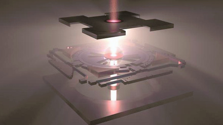
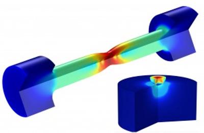
The image to the right shows a typical FEM outcome, plus micrographs of the free surface around an indent. The deformed region clearly contains many grains. The linear features within them are persistent slip bands, steps where hundreds of dislocations have reached the free surface. Dislocation motion on more than one slip system has been stimulated in grains near the indent, even though the plastic strains there are relatively low.
This region forms a pile-up, which is slightly out of focus in the optical micrograph. This material leads to pronounced pile-up formation. Grain rotations during deformation are apparent at the edge of the pile-up and as depressions at some grain boundaries.
Future prospects
The use of inverse FEM based on simulating thermo-mechanical processes to infer material properties (or other model input data such as residual stresses) has enormous potential. Similar approaches to that of indentation plastometry can be employed to infer properties such as creep characteristics and thermal conductivity.
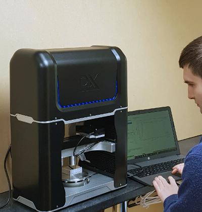
Furthermore, while indentation is a convenient procedure, the concept is applicable to any well-defined testing configuration. The improving availability and computational speed of FEM packages mean that such capabilities can now be deployed as routine tools, rather than one-off research techniques. Integrated products for implementing indentation plastometry are now becoming commercially available. The plastometer is a relatively small bench-top facility. The associated software is, of course, a key part of the product, with one package required for controlling the indentation and profilometery operations and another for obtaining the stress-strain relationship from the profilometry measurements.
The complete operation of indentation, profile measurement and output of a tensile (nominal) stress-strain curve takes about three minutes. There are also various other capabilities, such as outputting stress and fields during indentation and tensile testing and evaluating the critical strain at failure from a tensile ductility value input by the user.
Much development work is required for particular types of tests and target properties, but the potential benefits are such that some revolutionary changes to test methodologies are in prospect.
Academia feeding industry
These developments provide a good illustration of how academic research can stimulate industrial activities. While the concept of inverse FEM in general, and indentation plastometry in particular, has featured in many published papers over an extended period, the springboard for the emergence of Plastometrex was a decade of focused research in the Gordon Laboratory, within the Materials Science Department of Cambridge University.
This work, which was funded from a range of sources, was carried out by about a dozen PhD students, post-docs and collaborators, and is fully described in a series of about 20 publications. Several partnerships were created during this period, facilitating the identification of industrial needs and priorities in the area of mechanical testing.
These involved several types of organisations, from software developers to mechanical testing houses and potential end-users. Several case studies were undertaken jointly with some of these firms, leading to insights into key issues concerning both hardware and software aspects of the product.